|
||||||||||||||||||||||||||||||
|
||||||||||||||||||||||||||||||


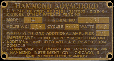
"Serial # 1256" This is approximately the 515th Novachord from a total of 1069 units made. Date of manufacture for this Novachord is roughly march 1940.
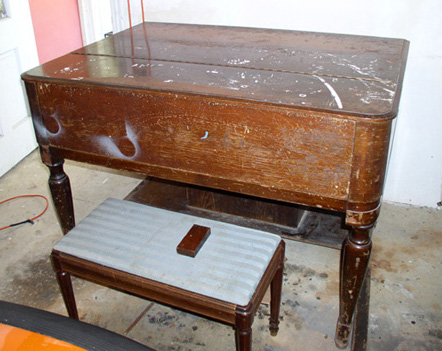
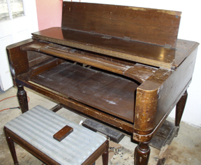
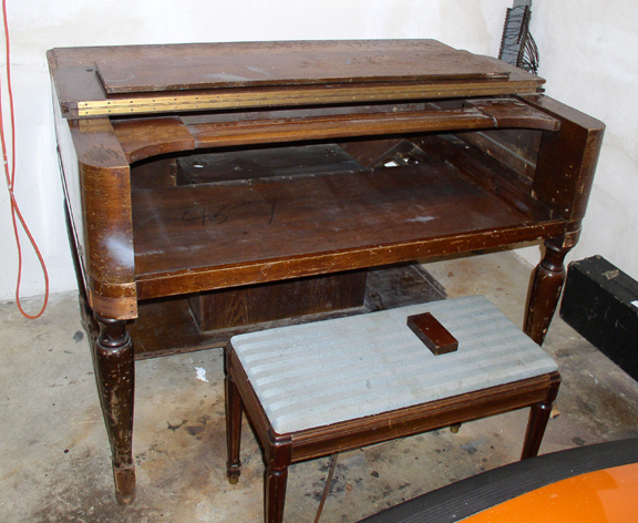
The Outer Case as it arrived at CMS. Very bad. On the other hand, most Novachord cabinets need refinishing anyway.
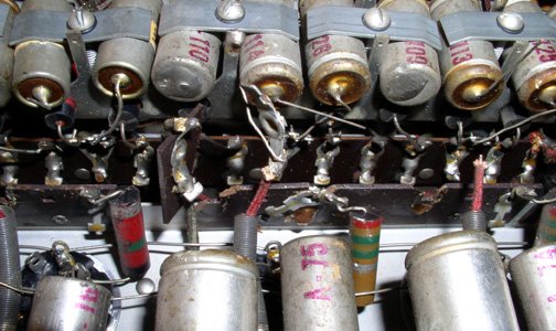
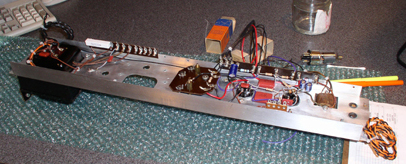
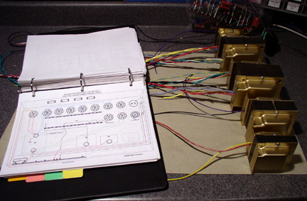
The Service Position - The Novachord has 2 major sections. The Lower Assembly and the Generator. The underside of the generator and the top of the lower assembly are shown in the above photo. The grim reality all 21st century Novachord owners must eventually face: All the custom value capacitors are unreliable, have increased in value and will continue to do so. The resistors from 1940 change value drastically depending on temperature and humidity. They all MUST be replaced. To replace just some components or even a section, would be a waste of time. This is a big job.
To make matters worse: A previous owner dropped this generator while it was disconnected, probably during moving, damaging many of the terminal strips riveted under the 9 channels that make up the body of the generator. To replace these strips, the channels needed to be removed. This is a massive undertaking. Warning! Don't try this at home kids!
If you subtract the wattage for the power amp that I'm not going to use, the AC power consumption is approximately 269 watts. Many people ask me - Why
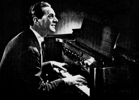
a Novachord? I am a big fan of vintage horror movie,
sci-fi and spaghetti soundtracks . In the last couple of years
I have been getting into tube synths - they have this particular
sound that I find very unique. I've been using my Solovox and
Clavioline for recording, and have gotten some amazing sounds
out of them by putting them through modern digital effects. The
Novachord is a polyphonic version of these instruments, so I am
hoping to get similar results.
Some recordings out of the past The Screen Gems theme - makes a great ringtone for your cell phone Here is the incredible Pedro Moequecho and his band playing a Gershwin tune From the album "Los Anos de la Alegria". Intro by Pedro Morquecho playing "Las Hojas Muertas" Here is Pedro Moequecho and his band playing "Bahia" Here is Pedro Moequecho and his band playing"St Louis Blues" From the album "El Fabuloso Novachord". This section has a typical spooky Novachord texture that was used for underwater sequences. Jerry Goldsmith's 2nd season theme for Voyage to the Bottom of the Sea One of my personal favorites. Some very unusual sounds happening here. from Harry Lubin's music for the Outer Limits episode - "The Duplicate Man" Expanded version featuring a superbly haunting Novachord & Trautonium duet at the end. This is from the famous episode featuring Robert Culp with the "Glass Computer Hand". Collins Driggs performing the Parade of the Wooden Soldiers Collins Driggs performing When the Day is Done From the 78 RPM record.
Movie and Television listings here
|
||
PHOTOS AND COMMENTARY OF THE RESTORATION PROCESS |
|||||||||||||||||||||||||||||||||||||||||||||||||||||||||||||||||||||||||||
|
|||||||||||||||||||||||||||||||||||||||||||||||||||||||||||||||||||||||||||
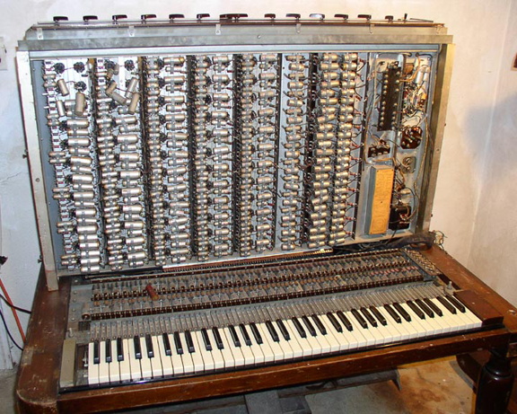
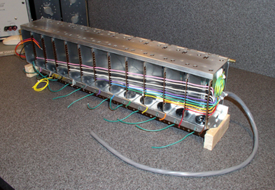
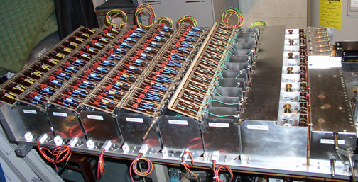
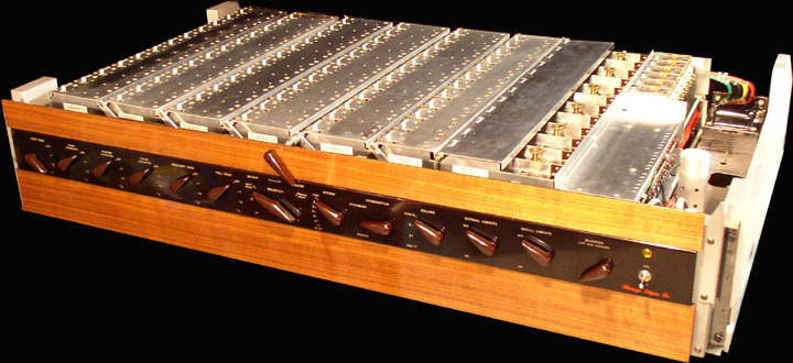
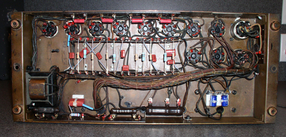
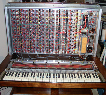
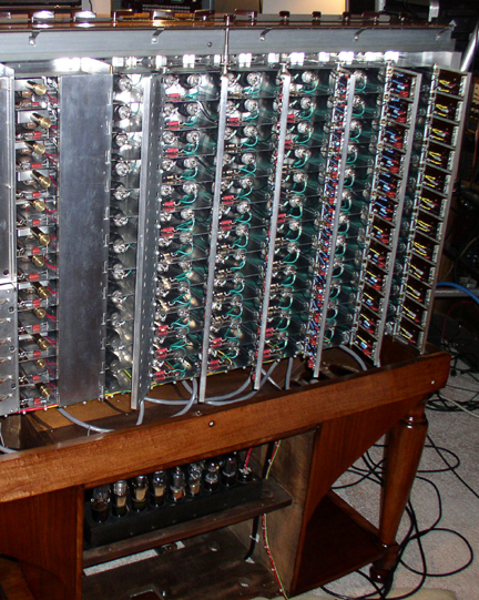
THE GENERATOR
The "brain" of the instrument
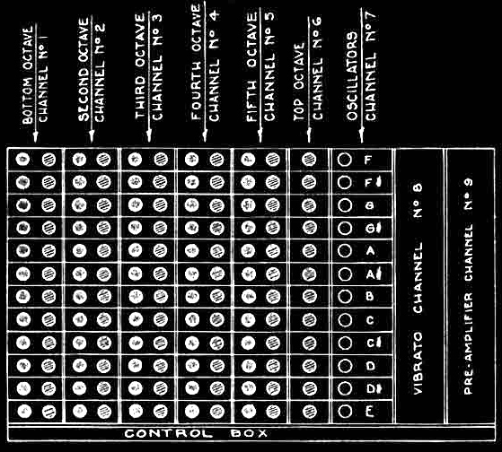
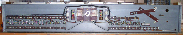
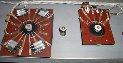
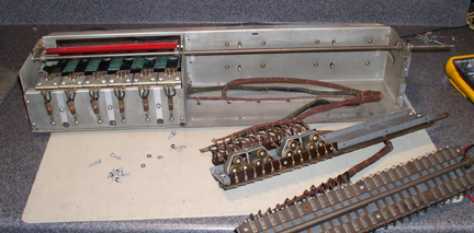
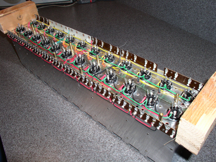
The massive "Generator" consists of the control box in the front, and channels 1 through 9 in the rear. All the audio processing in the Novachord is performed in the generator. The Control Box houses the controls for the instrument as well as all the passive audio processing circuits including the 5 resonators. Channels 1 - 9 house the active vacuum tube circuits. There are 12 oscillators, 60 frequency dividers, 60 band pass filters, 72 VCA's, a pre amp and a hex-vibrati in the generator. There are a total of 146 tubes in the generator.
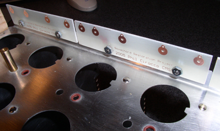
Stripping the underside of the generator.
The Control Box
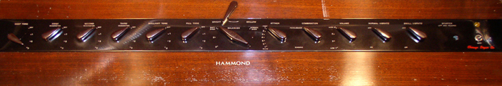
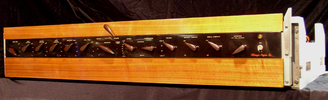
The Control Panel before restoration. The one saving grace about this particular Novachord is that the front panel is in good condition.
The Control Box internals before restoration - The rear section (shown above) contains the 18 channel passive mixer with it's Rube Goldberg mechanical keyboard volume balancer.
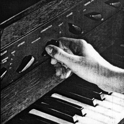
The preset mechanism - The Combination lever engages the 2 preset sounds of the Novachord. A cam that slides underneath the front panel sets all the controls to either the "Percussion" preset or the "Singing" preset. The "Percussion" preset is very close to a piano sound. The "Singing" preset is somewhat organ like.
The Resonator Filter Bank before restoration - The front section of control box (the control panel) houses the filters and the controls for the instrument. A combination of rotary switches sets the tone of the Novachord. From left to right: 1 low pass, 3 band pass, 1 high pass and 1 bypass.
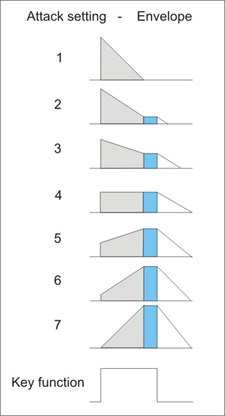
The Attack Control - On the left half of the above photo is the attack control. A seven position switch that actually adjusts the attack, decay and sustain of all 72 notes. The release is engaged by a foot pedal. This is one of the many features of the Novachord that place it in the domain of the synthesizer. And you thought the ADSR was invented in the 60's - not true. The control on the right is the volume control.
The Operation of the Envelope Generators is shown in the diagram above. The gray shaded areas are the attack and decay functions. The blue shaded area is the sustain voltage as the key is held down. The white areas are the release function engaged by the foot pedal after the key has been released. The times are not variable, but the levels are. Somewhat limited, but amazing for a pre-WW2 synthesizer. Setting 1 is for percussive type envelopes. Setting 3 looks like a typical synthesizer ADSR setting. Setting 4, without the release function is an organ envelope. Setting 7 would be great for string simulation. Please note that the release also works on setting 1 if the key is released soon enough.
The Control Box after restoration - I ended up replacing all the passive components.
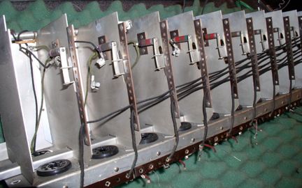
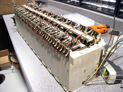
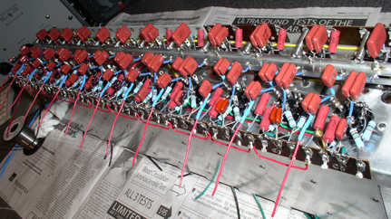
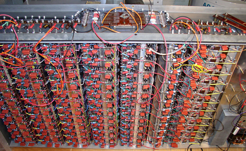
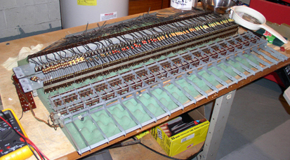
Restoration of the Individual Generator Channels 1 to 9
Disassembly of the Generator - Some kind of madman pulling out channel 2.
The 9 generator channels were tackled in descending order:
Channel 9 after restoration - The Preamplifier - gone are the nasty capacitors. There was a massive PCB oil filled capacitor in the center of this channel. But I suspect the real culprits of the contamination were the 2 "black tar" capacitors mounted alongside of the oil capacitor. The black goo that was leaking out of them was incredibly nasty. It had an awful smell and a very low boiling point. If a soldering iron got near the stuff, it started bubbling like crazy and emitting these nasty fumes. I never encountered anything like this, but I knew I didn't want it in my house. To clean the channel properly, I had to strip it to the chassis. While I was cleaning the "tar of doom" off of the chassis, I noticed it had one good quality - It polished the chassis to an almost mirror like shine. So, I polished the whole chassis with descending grades of steel wool. It looked and smelled much better. The preamplifier is a simple circuit compared to the rest of the instrument. So I knew at that point, I had a long long road ahead of me.
Channel 8 before restoration - There are 36 capacitors beneath the 3 X 12 pole switches. The wiring harnesses leading to the reeds and oscillators were composed of cotton covered wire that wreaked of PCBs. They all needed to be replaced.
Channel 8 after restoration - The Hex Vibrati - the 6 mechanical reeds in the back housing are always wiggling.They are engaged through 3, 12 pole switches to each oscillator so that when you play a chord - each note has a different vibrato rate. Individual LFO modulation of each note - nice. The red bar starts the reeds moving manually by a lever on the front panel.
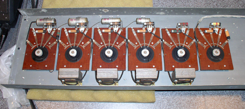
Channel 7 restored - This is the underside of the twelve oscillator circuits comprising the top octave tone generators.
This is the top of Channel 7 after restoration - the custom transformers have adjustable cores that are used to fine tune the instrument. Each compartment in channel 7 houses a transformer, a tube and a coarse tuning capacitor.
Channel 6 after restoration - This channel houses the twelve VCA's for the top octave. The loomed wire supplies the signals from the individual envelope generators in the keyboard. At this pont, I am planning to eliminate the spring connectors and use circular multi-pin AMP connectors instead.
Channel 5 before restoration.
Channel 5 after restoration - Each compartment houses a frequency divider tube, a VCA tube and a passive band pass filter under the lid. The hinge of the compartment has a switch mechanism that reduces the bandwidth of each band pass filter for the "mellow" setting. The first compartment has a pair of tubes in it for show. There are 5 channels like this one in the generator, each with 12 compartments, for a total of 60 circuits. Fun fun fun!
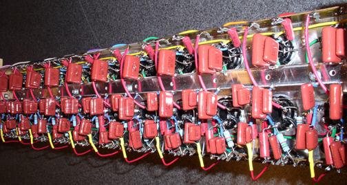
Channel 4 before restoration - the capacitors and the large resistor mounting bar have been removed.
Channel 4 during restoration - Here are some of the custom PCB's I made to replace the smashed terminal strips.
Channel 4 after restoration - This is the underside showing the polypropylene film caps and the metal film resistors. Many of the capacitors had to be doubled up to get the correct value specified by the factory. Also, due to tolerance limitations, all values and combinations of values had to be selected and verified on a digital capacitance meter. The 5 divider/vca channels end up using about 150 capacitors each.
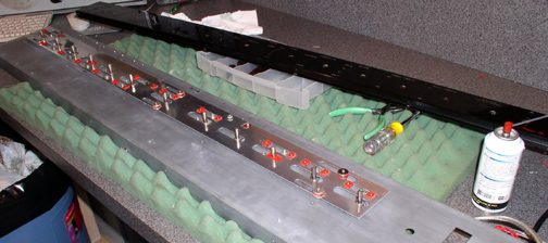
Channel 3 - during restoration - This is the chassis of channel 3 before polishing. The Novachord Restoration Project involves removing all the components, all the wiring, removing all the tube sockets, cleaning and polishing the chassis, installing the reconditioned tube sockets, installing new wiring, resistors and capacitors.
Why go this far? -
The primary reason I went so far with the cleaning, polishing
and rewiring was to protect my family's health.
Channel 3 after polishing and wiring - A large amount of elbow grease was required.
Channel 2 After restoration - A light at the end of the tunnel.
Channel 2 after restoration
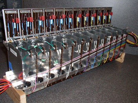
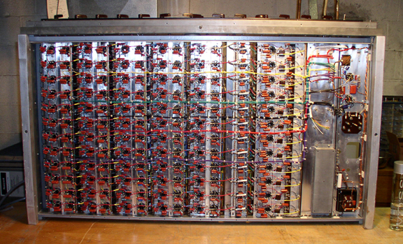
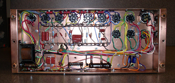
Channel 1 after restoration - The next step is to paint the generator frame and assemble the generator.
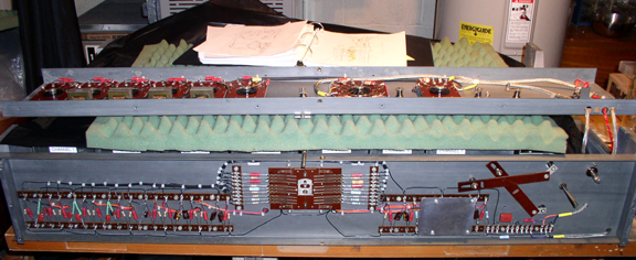
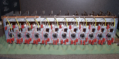
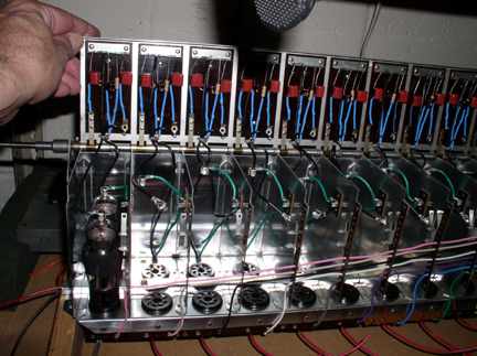
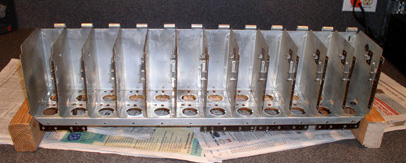
Assembling the Generator - The compartment lids are open.
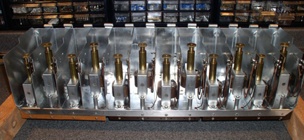
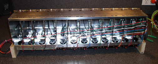
The underside of the Generator during assembly - The worst is over.
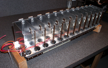
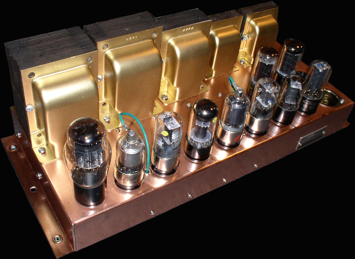
The Generator after restoration - All ready to go.
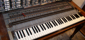
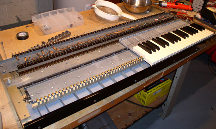
THE KEYBOARD
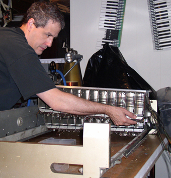
Keyboard Assembly - Here's a shot of the keyboard frame assembly during contact cleaning and restoration. Like the generator, it has many compartments. They house the multiple contacts per key and the cam that engages the release function of all 72 envelope generators. The engineering is quite intricate and advanced for 1938. It sometimes reminds me of working on my old V. W.- Porsche.
Assembling the keyboard mechanicals. The envelope generators were in the rear section.
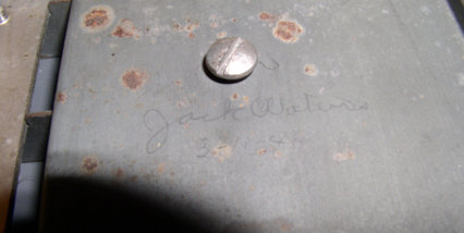
A message from the past - Jack Waters finished the keyboard assembly on 3 /11/ 1940
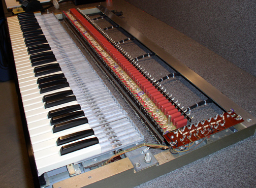
The Keyboard Assembly after restoration - I used the Altium PCB program to design custom circuit boards for the key circuit. 12 PCB's were mounted on top and bottom of the front component rail. The rear component rail, as well as the spring connector assembly were removed. 7 AMP connectors were installed, 1 for each octave and 1 for the keyboard power to facilitate transportation (ha ha). Note the 144 capacitors.
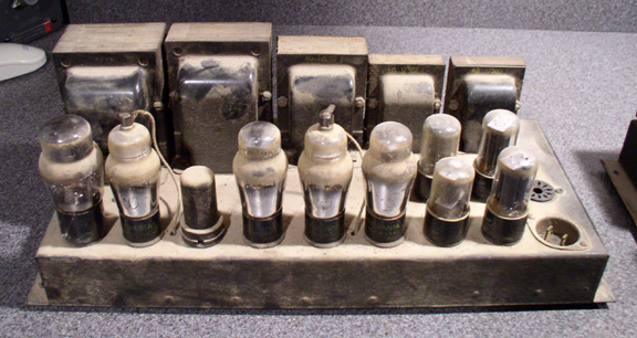
THE POWER SUPPLY
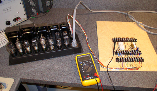
The Dummy Load -
A fellow Novanaut, Stephen Kamm gave me his recipe for a dummy
load, so I can check the voltages coming off the power supply
before I hook it up.
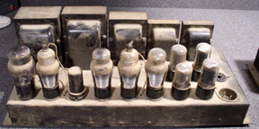
The underside of the power supply - The passive components were replaced at the start of the NRP. All the cotton covered wiring needed to be replaced to eliminate the contamination.
Underneath the rebuilt power supply - Just in case you haven't figured it out yet, this was a massive project in itself.
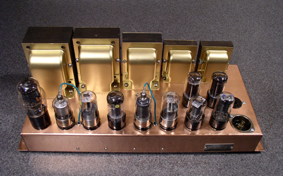
The rebuilt power supply - The outside was polished with steel wool and clear coated. The transformer bells were stripped and painted.
Extensive documentation was necessary as the power supply was taken apart to be able to wire it up correctly again. Also the transformers had to have their bells removed and reconditioned. The contaminated wire was removed at the winding connections and replaced with high temp wire. Insane, I know.
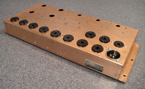
The Copper Plated Chassis - Huh? Yes, it's true. It was very difficult to remove the rubberized paint from the chassis to expose the copper finish. The plating was quite thick however. The nameplate says it was made by the Rauland Corp. Many early Hammond amplifiers were made by Rauland and Webster. In my opinion, Rauland made a better instrument.
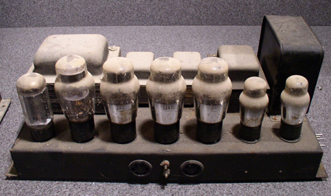
The Field Coil Power Amplifier - These are highly regarded in tube amp circles, but the two 12" speakers just can't cut the high end. Here it is before a cleanup. This amplifier was also made by Rauland.
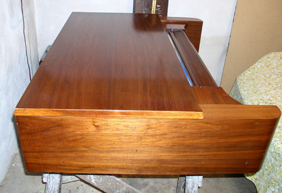
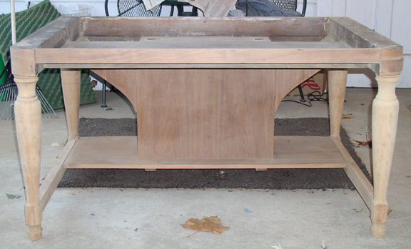
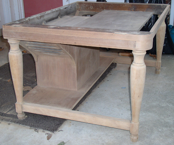
THE CABINET
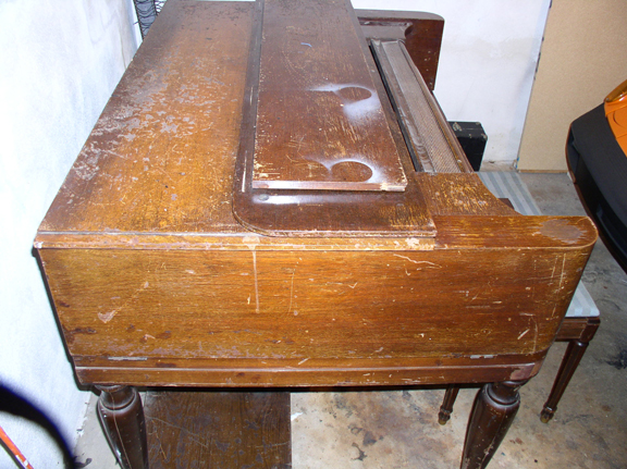
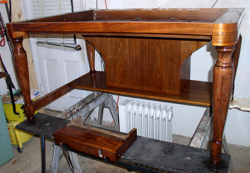
Sick Puppy! - Here is the cabinet with the keyboard and generator removed. That is not a Novachord bench. Hope to find one one day.
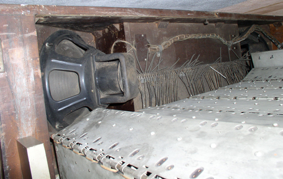
A peek at the speakers - Pictured in this photo are the 2 Jensen field coil speakers, wiring harness and the 72 spring connectors. This photo was taken early on before disassembly. The boxes in the lower area of this photo are the lids of the generator as it stands upright in the service position.
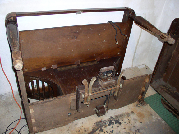
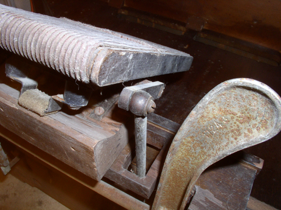
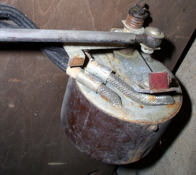
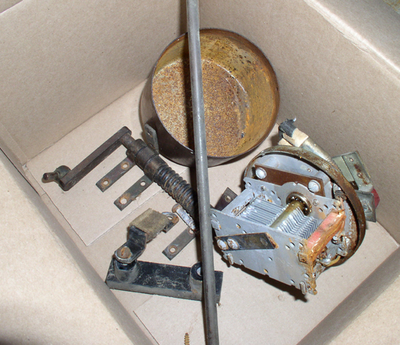
The underside of the lower cabinet - You can see the sustain pedals and the expression pedal. The expression pedal has a connecting rod that travels to the large variable capacitor that sits underneath the power amplifier shelf. Large shielded cables connect this capacitor to the preamplifier in the generator.
Aye, she looks like she's been at sea! - Extensive restoration was required in the lower sections due to moisture damage.
The expression pedal connecting rod - has a ingenious self adjusting mechanism.
Specialized parts - ball bearings and gears drive the variable capacitor inside the shielded housing.
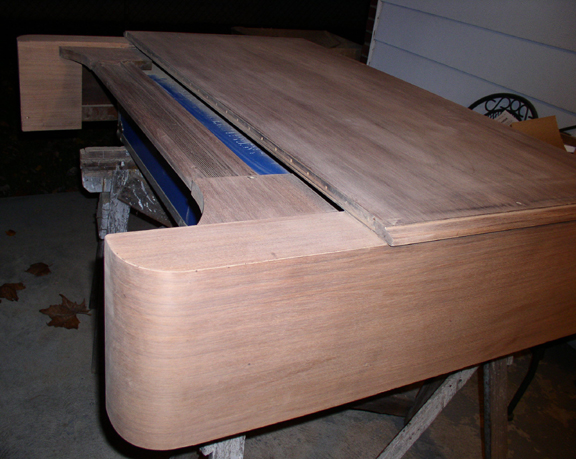
The generator cover - before and after! - Amazingly, Most of the cigarette burns, Cocktail rings and scars sanded right out. Nearly all of the veneer was intact.
After sanding - I discovered that the legs and the braces are made of a softer and lighter hardwood. These sections required staining so as to match the mahogany veneer on the other sections of the Novachord.
Sanding past the stain - The veneer was quite thick, so it was possible to sand off the stain without burning through the veneer. This took a incredible amount of hand sanding.
The speaker grilles - These sections were a notable pain in the neck. Sanding off the stain in between the nooks and cranny's was quite labor intensive and time consuming.
Multiple coats of finish on all surfaces - 7 to be exact. This made me grateful that I am an electronic tech and not a woodworker by trade - to put it nicely.
The generator cover during finishing - It turned out much better than I ever expected considering it once looked like it went through a war.
|
|||||||||||||||||||||||||||||||||||||||||||||||||||||||||||||||||||||||||||


POWERING UP THE RESTORED NOVACHORD
Making the final connections
Installing the tubes
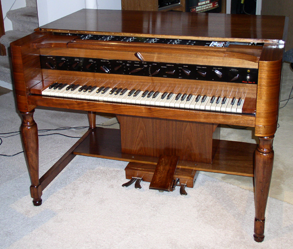
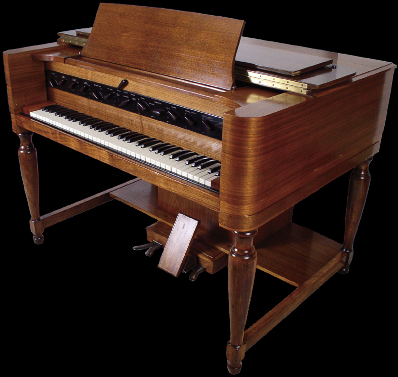
The Novachord after restoration - The Novachord was first powered up at 10:30 PM on December 1, 2005. The front lid and the music rack were still undergoing restoration at this point.
My band member Burton was over for band practice that turned into the Novachord launch. I sat there and talked with him as I installed the 146 tubes in the generator. I have to admit, I was a little scared to turn it on. I think I was stalling by checking and cleaning things. "Stop cleaning the thing and turn it on" he said. I flipped the switch and all the tubes started to glow. Check the voltages - all correct! Scope an oscillator - Working! Scope the output - Its playing notes! OMG. All these sound clips are single takes - no overdubs. Here are the first spooky sounds it made 12 / 1 / 2005 11:00 PM This may frighten small children. Novachord Improvisation #2 12 / 2 / 2005 2:30 AM This is how it sounds after being partially calibrated. Most of the notes are playing in tune and it sounds freaking amazing. Novachord Improvisation #3 12 / 3 / 2005 8:30PM This is the first part of #3. I honestly never thought the instrument would sound this damn good! Novachord improvisation #5 12 / 6 / 2005 This excerpt from #5 illustrates the range of the attack control - I know, I am an echo freak. Novachord improvisation #9 12 / 11 / 2005 This is the first part of #9. This is the Nova through the Bode 6552 frequency shifter. This is a Hammond Solovox ala Cirocco all sound files & compositions ©2005-2007 Phil Cirocco
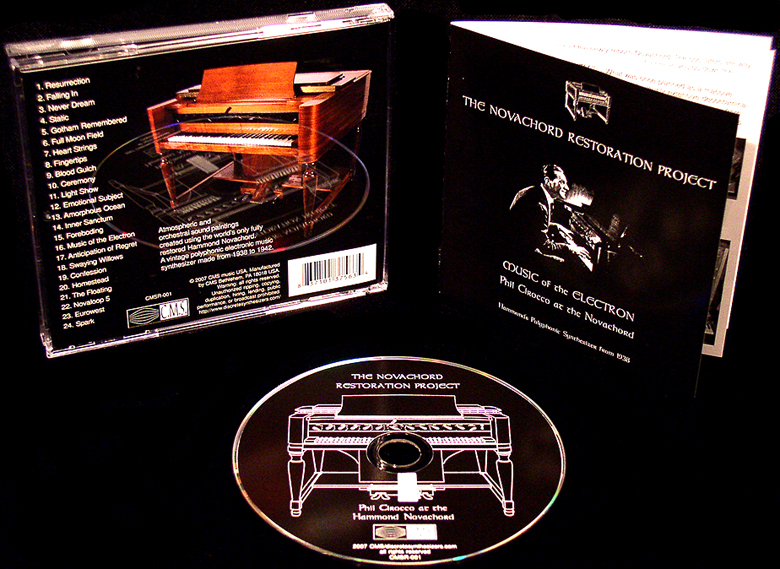
If you would like to own the better sounding, full versions of these compositions, a full length CD is now available.
The CD is now available at "CD Baby" for a special reduced price!
News Flash - The sample CD has been cancelled! This Novachord has been sampled and is available through Sonic Couture here
Email Project Manager / Novachordist Phil Cirocco here
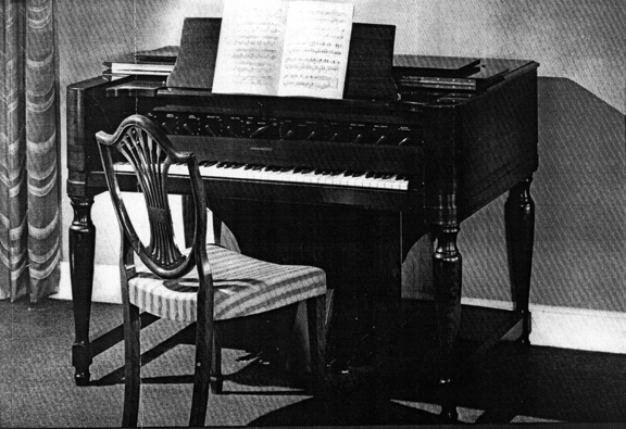
The restored Novachord complete with the lid and music rack.
Conclusions: 1. - It's a synthesizer - Based on the old recordings I have heard, I was expecting a cross between an organ and a synthesizer. As you can hear from the sound files - It's a synthesizer! 2. - The direct output sounds great! - The balanced XLR output I installed in the preamp section drastically improved the sound of the instrument. Thanks to Mike Dal Sasso for advice on this. I am sure the speakers and enclosure really did give it a piano like quality, but I suspect the lack of high frequency response (tweeters) impeded the sound of the instrument. Probably the major reason why the instrument never caught on was the lack of any other audio equipment available at the time. 3. - The oscillators and dividers are very stable -There has been no perceptible pitch drift whatsoever - From stone cold to being on for 7 hours. I haven't touched the tuning adjustments since the first calibration. Considering how much the temperature changes inside, it's quite remarkable. Most of the tubes running in my Novachord seem to be original Sylvanias but there is no way to verify this. 4. - Modifications - Component values as well as circuit design were not altered or modified. Changes: 1. - The keyboard circuit parts locations - the smaller size of modern parts made this necessary. 2 - The keyboard to generator hookup scheme - The 72 springs were just completely off the wall. 3 - I did not use that awful cotton covered wire. Everything else was to factory spec. 5. - Thousands of passive components must be replaced. A warning to those who tread in my footsteps. I am not being negative here - just blunt. These are the harsh realities of Novachord restoration. This was an incredibly massive job! Don't embark on it unless you can handle it. For those of you who think you don't have to restore your Novachord, keep this in mind - The positive rail is at 300v DC. The negative rail is at -300v DC. With more than 1000 70 year old capacitors across those rails, the failure probability factor is nearly 100%. Keep a fire extinguisher on hand. 6. - A final warning: - Wait, it gets even worse. I love the instrument so much, so I hate saying this, but I feel obligated to warn people again about the toxic issue. If you have one, or you are considering buying one, please keep in mind that It might need a total decontamination. What's the reason for this contamination? I suspect that over the years, the large PCB oil filled capacitors inside the generator, power supply and amplifier, emit vapors that condense on all the surfaces inside the instrument. When the instrument reaches operating temp, it releases copious amounts of these fumes from all the surfaces of the instrument. Nasty.
Email Project Manager / Novachordist Phil Cirocco here
|
||
|
|||||||||||||||||||||
|
|||||||||||||||||||||